
How to Replace, Offset, and Collimate a Secondary Mirror
It's not uncommon that a low quality, small or a badly attached secondary (diagonal) mirror ruins a telescope with otherwise perfect optics. This article gives an example of a Newtonian telescope secondary mirror's replacement, offset calculation, collimation, star testing.
When to Replace a Secondary Mirror
There might be a several reasons to replace or re-attach a diagonal mirror of a Newtonian:
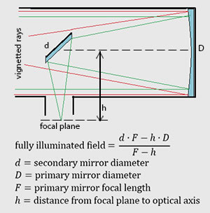
Example of vignetting (shown in red) and calculation of the fully illuminated field of view
1) The stock mirror is often too small and causes vignetting (darkening) even at the center of field of view. This happens because some manufacturers are trying to achieve mutually exclusive features: A short, fast OTA with a long back focus and a small central obstruction. This issue can be diagnosed by looking through an empty focuser exactly from the focal plane - if you can't see the whole primary mirror reflection (including its clamps as seen in this image) - then the diagonal is too small. Or calculate if the fully illuminated field of view is less then zero. The solution can be either to move the primary mirror further away from the secondary (often not applicable) or to increase the secondary mirror diameter.
2) The telescope is used for deep sky astrophotography and a larger secondary mirror is required to achieve a wide fully illuminated field of view.
3) The stock mirror is attached in a such way that it's under mechanical stress, which causes astigmatism and image degradation, as described here.
4) The offset of the secondary mirror isn't set correctly, which results in unevenly illuminated field of view and complicates the collimation process.
5) The stock mirror is of inferior quality and, usually, causes astigmatism.
6) The mirror is too old and needs to be re-coated or replaced.
Removing the old Mirror
In my case I had to replace the stock 58mm diagonal of my Skywatcher 10" Newtonian with a larger 63mm one because it was too small. I'll describe the process here.
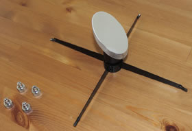
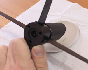
Spider removed from the OTA
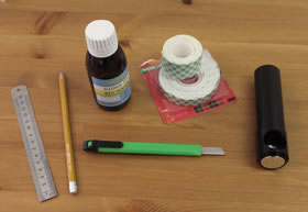
Tools required to replace the mirror
First stage is to calculate the required mirror diameter, while the basic idea is to decide which vignetting can be tolerated at the edges of the field of view. For example, "less then 80% at the edge of a 30mm chip". I've simulated the vignetting using "ISACC" program, and there are other online calculators available such as this one: BBAstroDesigns. The very least for visual observing is to make sure that the center of the field of view is illuminated, meaning that fully illuminated FOV is higher than zero (the equation is shown in this image)
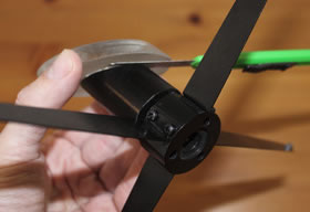
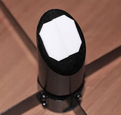
Detaching the secondary mirror
The tools required for the replacement procedure are fairly simple: A pencil, a ruler, a long sharp knife, alcohol (or another cleaning solution), a double-sided foam mounting tape and collimating tools. The tape is a key factor and it should be a quality product: Strong, not too soft and not too hard. I've always used a "Scotch Indoor Mounting Tape" with a green pattern (shown above) for my scopes and haven't encountered issues so far.
In order to remove the old secondary mirror, we should unscrew the four nuts which hold the spider inside the OTA and remove the whole assembly. The mirror itself is attached to its holder either with clips or with some form of adhesive (in my case a double-sided foam tape). We can pre-cut the adhesive or the foam using a sharp, thin knife and gently pull the mirror off.
Calculating the Secondary Mirror Offset
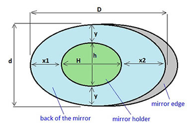
Elliptical flat mirror and its holder placement with offset
Elliptical mirror offset
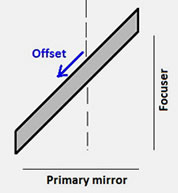
The "classic" method for the secondary mirror placement is to "offset" it away from the focuser and towards the primary in order to achieve a uniformely illuminated field of view. The offset in each direction = secondary_diameter / (4*focal_ratio). The actual offset in the mirror plane (marked by a blue arrow) is this number multiplied by a square root of 2.
Marking the mirror holder location
To mark the location for the mirror holder we should measure the following parameters: Secondary mirror major axis (D), minor axis (d), holder base major axis (H), minor axis (h), as shown in the figure above.
Distances between the holder and the mirror edges (x1, x2 and y) are calculated like this:
Offset=(1.41*d)/(4*focal_ratio)
y=(d-h)/2
x1=[(D-H)/2]-Offset
x2=[(D-H)/2]+Offset
We assume that the mirror holder center coincides with the central axis of the OTA (usually true for a round holder suspended on a symmetrical spider). Note that a small inaccuracy of 1-2mm is tolerable since it will be compensated during collimation process.
Attaching the New Mirror
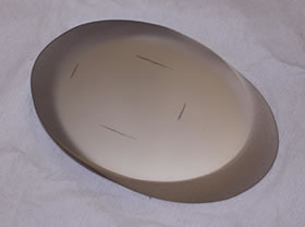
We can carefully place the new mirror with its reflective surface down on a sheet of a soft paper (the one it was shipped with or a paper towel). Using a ruler and a pencil we can mark the mirror holder location. A care should be taken not to slide the mirror over the paper.
Double-sided mounting foam tape
There are various methods of attaching the mirror to a holder without clips: One is to use an aquarium silicone sealant which is applied to 3 evenly spaced spots or to a large single central spot. In this case the distance between the mirror and the holder should be controlled with matchsticks and the adhesive should be allowed enough time to set.
Another method is to use a double-sided foam adhesive tape. It is faster and used by many manufacturers (Skywatcher, GSO), though it's arguably weaker and often avoided when attaching heavy mirrors for large telescopes. Special care should be taken when choosing the tape - if it's too soft it won't be strong enough and if it's too hard it won't be elastic enough. The tape patch shouldn't be too small in order to provide enough grip but also not too large so it won't introduce stress. A safety feature can be added by attaching a short, strong string between the mirror and its holder using a strong epoxy. This will prevent the mirror from falling in case the adhesive fails.
Attaching the new mirror to its holder
Methods which involve covering a large surface of the mirror with adhesive (or tape) or using non-elastic adhesives (such as epoxy) should be avoided, since they may introduce mechanical stress which can bend the mirror and cause an astigmatism.
I've attached my mirror using "Scotch" indoor mounting tape. First I cleaned the mirror back and the holder surfaces with an alcohol and firmly attached an exposed 25x25mm tape pad to the holder. Then I've aligned the mirror holder assembly against the new secondary mirror and carefully attached it between the markings. Note that it's easier first to align the mirror on a square sheet of a tissue paper and then to align the spider relatively to the paper. The next part was to firmly press the secondary mirror against the holder. I simply pushed it against the mirror while it's still lying on the tissue paper (this left no marks or scratches). If you are uncomfortable doing it - you can find a different method - for example to firmly hold the mirror by its edges.
The last stage is to insert the secondary mirror assembly back into the OTA and to collimate the telescope. Note that in this article I've only given an example of how I glued my mirror, and I can't guarantee that it will work for others. The only way to be safe is to use mirror clamps, or at least (if you own a really expensive primary mirror), add a safety string.
Collimating the Secondary Mirror
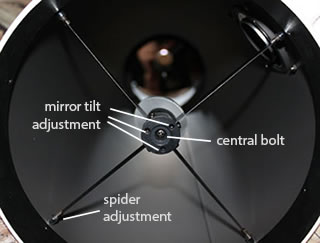
Adjustments of a secondary mirror
This is an example of a basic procedure of secondary mirror collimation mostly intended for a visual use. For this task we need a collimating tool such as a Chesire eyepiece or a collimation cap. The tool must allow us to see the edges of the secondary and the whole primary mirror reflection (as seen below). In my case a Cheshire wouldn't allow it and I had to use a collimation cap.
The first stage is to center the mirror holder relatively to the central axis of the OTA. If we assume that the mirror offset was set correctly and the mirror holder is centered with the spider - we can simply adjust the four vane spider in a such way that the opposing vanes are parallel and form a single line. This also ensures that there won't be any split diffraction spikes (actually we can fine-tune this adjustment by looking at a bright star and making sure that spikes aren't split). If a more accurate alignment of the diagonal relatively to the focuser is required, it can be performed by adjusting the spider while measuring the distances between the mirror edges to the OTA, taking offset into account. But then the vanes might become non-parallel.
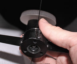
Holding the mirror during adjustment
The next stage is to center the secondary mirror relatively to the focuser by adjusting its rotation and the fore-aft position (closer-further from the primary mirror). Usually there is a large central screw which adjusts the fore-aft position and three smaller screws around it which adjust the tilt. Here comes a little trick: I released all three small screws (allen in my case) and held the freely moving mirror holder with my hand in a such way, that the primary mirror edge reflection (3) was concentric with the secondary mirror edge (2). In order to do so I had to slightly tilt and rotate the mirror. While retaining this position with one hand I adjusted the central screw untill the secondary mirror edge (2) was concentric with the focuser/Cheshire tube edge (1). Then, while still holding the secondary, I slightly tightend all three allen screws to fix the achieved position .
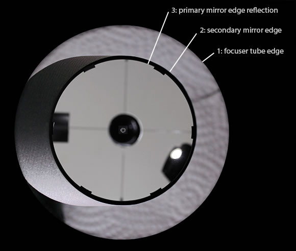
View from the focuser when collimating the secondary mirror position and tilt
Now we can release the holder and make fine tuning adjustments to the mirror tilt. The three small screws should be adjusted untill the secondary mirror edge (2) is concentric with the primary mirror edge reflection (3). Make sure that the screws are relatively tight so the mirror is held firmly, but not overtightened so they won't "dig" into the aluminium holder.
Sometimes we will see that after adjusting the secondary mirror tilt - the mirror isn't exactly aligned within the focuser tube. We can repeat the previous steps or, if the misalignment is small, just let it be, since this won't have any dramatic effect on our image apart from slightly asymmetric vignetting at wide angles. This may happen because we haven't accurately centered or offset the mirror, or the mirror holder rotated while we adjustment the tilt.
The last stage of the collimation process is to adjust the primary mirror tilt (preferably with a Cheshire eyepiece rather than a laser collimator). Note that for an average visual observer the importance of collimation goes in the following order (from high to low): Primary mirror tilt, secondary tilt, secondary position relatively to the focuser, focuser tilt. Therefore we shouldn't sweat over a slight inaccuracy of the offset for example.
Testing the Telescope for Astigmatism
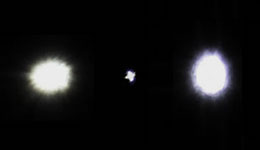
A simple star test can reveal astigmatism
We should perform a simple star test to check for astigmatism, which is often the optical aberration caused by bad secondaries or pinched optics (which become slightly "cylindrical"). If it's present - the out of focus star images will appear elliptic and the focused image will look like a "cross". There are three options to consider:
1) Unless it was tested before, the primary mirror can be the cause of astigmatism. It can be tested by marking the direction of the astigmatism relatively to the focuser, and then disassembling and rotating the primary mirror (or the whole cell) by 45 degrees relatively to the optical tube assembly. In case the astigmatism direction rotated as well - the primary mirror is the problem. Either it was held too hard and pinched by its clamps or even glued to its cell (in this case slightly release the clamps or unglue the mirror), has insufficient support points (can be tested by performing a star test at low elevation), or the optical quality is the problem.
2) The secondary mirror is under mechanical stress and we should re-attach it using another method (a different / thicker / more elastic adhesive, using smaller gluing spots, etc.). In this case after re-attachment the astigmatism should disappear, or at least decrease.
3) If neither the primary mirror or the attachment methods are at fault - it means that the low optical quality of the diagonal is the cause for astigmatism and it should be replaced.
Remember that if you have an eyesight astigmatism issue - eliminate it by slightly rotating the head during the star test procedure and see if the astigmatism direction follows.